
Experimental Lab
The experimental lab at Systems and Control is geared towards introducing students to hardware and software that implement control theories learnt as part of coursework. A variety of setups based on mechanical, electrical and chemical principles are made available to the students for this purpose. As part of core coursework all masters students are expected to understand modelling, communication, sensor calibration and control of hardware to accomplish different control objectives. In addition, several graduate students carry out a part of their research on these setups to validate control designs. As the group evolves and interests of the control community change, the specific setups that are part of the lab undergo upgradation or changes.
Following is the list of Facilities avalaible with us:
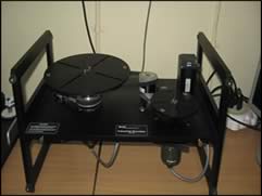
Industrial Plant Emulator
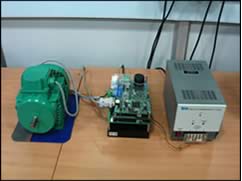
Induction Motor
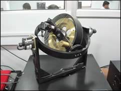
Gyroscope
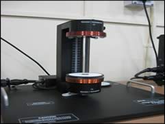
Magnetic Levitation
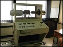
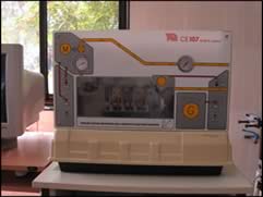
Gas Turbine
Engine Speed Control
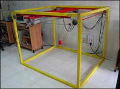
3D Crane
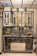
Hybrid Two Tank Setup
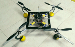
Quadcopter
